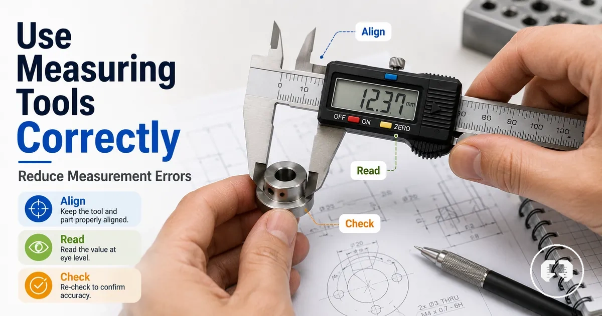
Using precision measuring tools for accurate and repeatable measurements
Using precision measuring tools starts with a controlled measurement process that reduces avoidable variation before a reading is accepted. Accurate measurement depends on stable conditions, correct preparation, controlled contact, correct handling, careful reading, repeatability checks, and appropriate after-use protection. The final result can vary by tool type, workpiece material, operator technique, and the measurement environment.
Precision measuring tools support accurate measurement and repeatable measurements when tool use stays consistent. A caliper, micrometer, or gauge may provide reliable results only when the measuring surfaces, workpiece, and reference conditions remain suitable throughout the measurement process. Small changes in contact, alignment, or reading behavior can increase the risk of measurement errors.
Careful use focuses on controlling each stage of the measurement rather than relying on the tool alone. Stable setup, proper preparation, correct handling, and disciplined reading work together to improve repeatability. Repeating a measurement under the same conditions can help confirm whether the observed value is consistent enough for the intended task.
The following sections explain how stable conditions, preparation, controlled handling, correct reading, repeatability, and after-use care contribute to accurate use of precision measuring tools. Each topic builds on the previous one so the measurement process remains clear without expanding into detailed calibration, purchasing, or troubleshooting guidance.
Stable conditions for precision measurement
Stable conditions are the starting point for accurate precision measurement because they reduce avoidable variation before a reading is taken. Stable conditions depend on the measurement environment, tool condition, workpiece stability, and reference consistency. They support more consistent results, although the final measurement may still vary with the tool, material, operator technique, and application.
Stable conditions for precision measurement become easier to maintain when the setup remains consistent from one reading to the next. For broader guidance on related measuring practices, see the precision measuring tools hub. The image below highlights the key setup conditions that help reduce unnecessary variation before measurement begins.
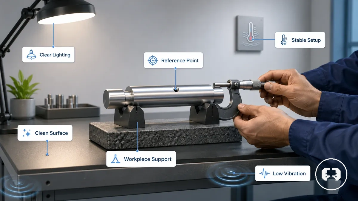
Environmental and setup conditions can influence measurement results before the measuring faces contact the workpiece. Temperature changes, vibration, poor lighting, contaminated contact surfaces, tool settling, workpiece movement, and inconsistent reference consistency may all increase variation. Practical workshop control aims to reduce these influences, even though it differs from laboratory-level control.
Before taking a measurement, confirm that the setup is as stable as practical:
- Support the workpiece securely to minimise movement during measurement.
- Keep measuring faces and clean surfaces free from dirt, oil, or debris.
- Allow the tool and workpiece to settle when recent handling or environmental changes may affect the result.
- Use clear lighting so the reading can be interpreted consistently.
- Reduce unnecessary vibration and maintain reference consistency throughout the measurement.
Stable conditions help reduce avoidable variation, but they do not replace correct tool reading or calibration. Those remain separate parts of achieving dependable precision measurement.
Preparing the tool, reference, and workpiece
Tool preparation makes the measured value more trustworthy before the tool touches the workpiece. Aligning the tool, reference point, and measuring surface establishes an acceptable starting condition that can reduce error before a reading is taken.
Preparing the tool, reference, and workpiece helps confirm that the measurement begins from a consistent baseline rather than an uncertain one. The illustration below highlights the preparation points that align the tool, reference point, and contact area before measurement starts.
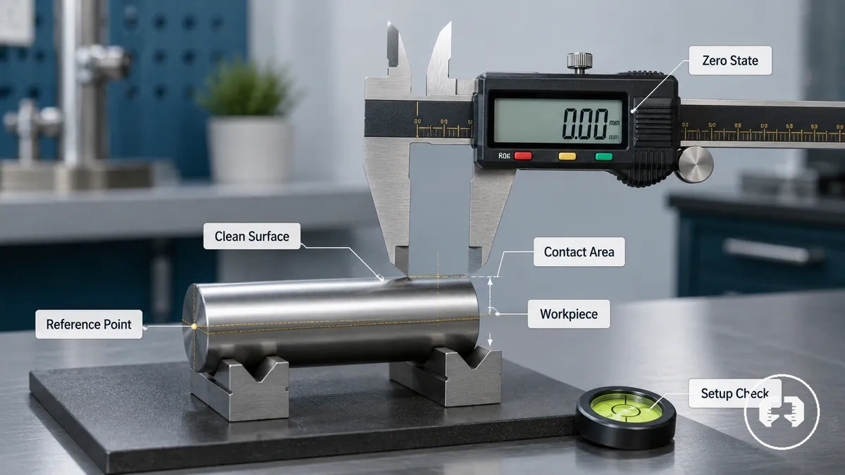
The preparation principle remains consistent even though the setup check may vary by tool type. A digital caliper may require confirming its zero state before measurement, while a micrometer may require checking its reference position. A depth gauge and a dial indicator also depend on a suitable reference point and clean measuring surfaces so the reading begins from an acceptable starting condition with reduced error.
Before taking a measurement, confirm that the tool, reference, and workpiece are properly aligned:
- Inspect the measuring surface and workpiece for dirt, oil, or debris.
- Confirm the tool is at the correct zero state or reference point.
- Position the workpiece so it remains stable during measurement.
- Check that the contact area is clean before the tool touches the workpiece.
- Complete a final pre-measurement check to verify an acceptable starting condition.
Careful tool preparation can reduce measurement risk and improve repeatability, but it does not replace correct reading technique or calibration when those are required.
Clean measuring faces and contact surfaces
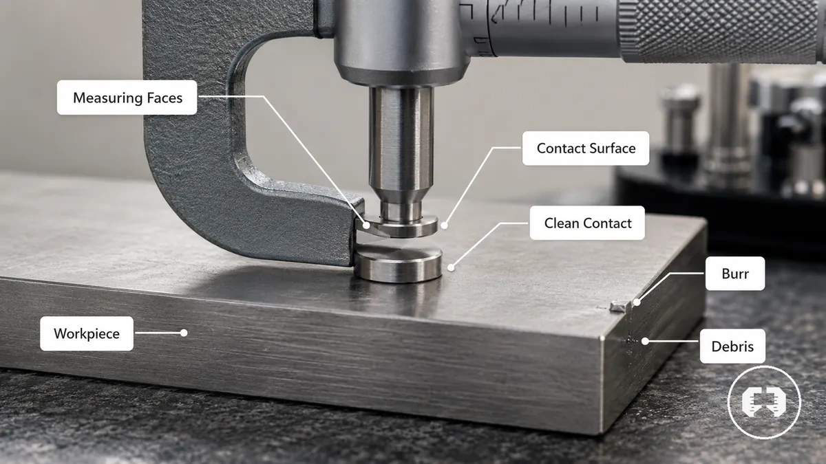
Measuring faces and contact surfaces should remain free from dirt, oil, burrs, chips, and visible damage before measurement begins because unwanted material can interfere with proper contact and increase the risk of a false reading. Clean measuring faces and contact surfaces support more consistent contact with the workpiece, although the effect of a surface defect may vary by tool type, material, and application.
Clean measuring faces and contact surfaces are shown in the close-up image below to identify debris-free contact, the workpiece surface, and a possible burr location before measurement begins. For example, a small burr or chip on the workpiece may prevent full contact with the measuring faces and create a false reading, while a clean contact area can improve repeatability.
- Inspect measuring faces for dirt, oil, chips, or other debris before contact.
- Check contact surfaces for burrs or visible damage that may affect the measured value.
- Confirm the workpiece surface is clean where the measuring faces will make contact.
- Remove loose debris before taking a reading to help reduce repeatability risk.
Zero position and reference checks
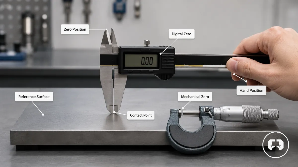
Zero position and reference checks confirm that the tool starts from the correct baseline before measurement begins. A reference check depends on the tool type and measurement mode because digital zero, mechanical zero, and reference surfaces may require different verification methods before a reading is taken.
Zero position and reference checks are shown in the annotated example below to illustrate the baseline before measurement. A basic zero check can help reduce the risk of carrying a starting error into every measurement, although a tool may still require calibration when higher measurement confidence is needed.
Complete the baseline verification before measuring:
- Confirm the digital zero or mechanical zero matches the expected start point.
- Place the tool against the correct reference surface or a known reference when appropriate for the measurement mode.
- Check that the displayed or indicated starting value is consistent before contacting the workpiece.
- Begin measurement only after the baseline appears suitable for the intended task.
A tool can pass a basic zero position or reference check while still requiring calibration if measurement accuracy is critical.
Correct handling during measurement
Correct handling during measurement helps reduce unwanted variation while the tool remains in contact with the workpiece. Correct handling combines controlled contact, alignment, stability, and disciplined reading, although the handling method may vary by tool type, measurement range, and the measured feature.
Correct handling relies on a stable grip, suitable contact pressure, consistent tool angle, reliable workpiece support, proper jaw or spindle seating, and clear scale visibility. Maintaining these conditions throughout the reading helps determine whether the measured value should be accepted or remeasured.
Follow this handling sequence while taking a measurement:
- Hold the tool with a stable grip that supports controlled movement without disturbing the workpiece.
- Apply contact pressure appropriate for the tool so the measuring faces seat consistently on the measured feature.
- Keep the tool aligned with the workpiece and maintain steady workpiece support throughout the measurement.
- Confirm the jaws or spindle are seated correctly and keep the tool angle consistent before checking scale visibility.
- Read the display or scale without changing hand position, contact pressure, or alignment.
- Remeasure if the tool shifts, seating changes, alignment is lost, or repeated readings differ.
Correct handling may differ between a caliper, micrometer, or indicator because contact conditions and measuring technique vary. When a reading appears inconsistent, remeasure under the same handling conditions before relying on the result.
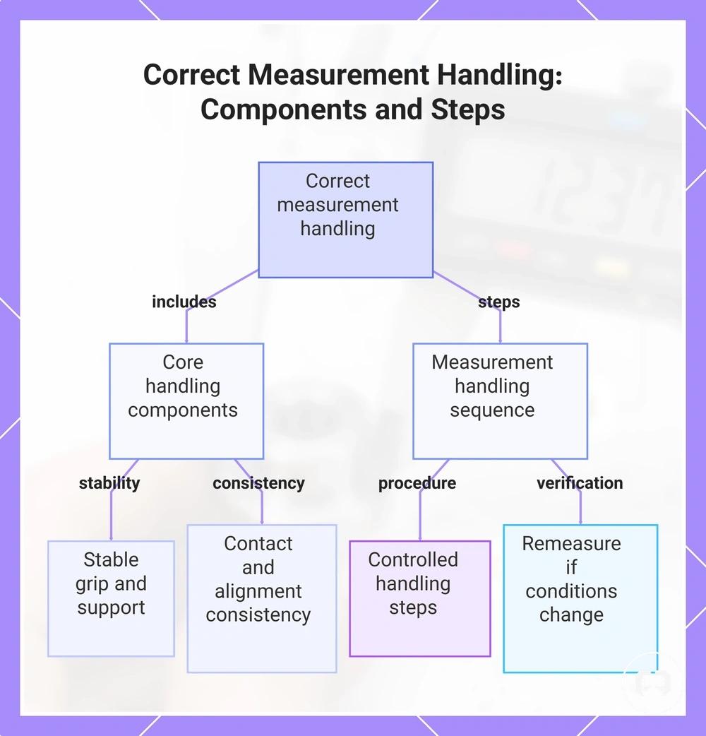
This chart shows the key components and the recommended sequence for correct handling during measurement, helping to reduce variation and ensure reliable readings.
Measuring force and contact pressure
Measuring force and contact pressure can change the measured value when contact is too light or too heavy because stable contact affects repeatability. The appropriate contact pressure depends on the tool type, material, and measured feature, so the same measuring force may not suit every application.
Contact pressure differs between calipers, micrometers, and indicators because each tool establishes contact differently. A micrometer may use a ratchet or friction thimble to help apply more consistent measuring force, while calipers and indicators rely on controlled contact, stable alignment, and suitable handling to reduce the likelihood of part deflection or tool flex.
The comparison below highlights the difference between firm seating and forced clamping during measurement.
| Firm seating | Forced clamping |
|---|---|
| Uses controlled measuring force to create a stable contact condition. | Applies excessive contact pressure that may increase part deflection or tool flex. |
| Can support repeatability when the measuring faces remain properly seated. | May increase the risk of a false reading because the contact condition changes. |
| Maintains contact without unnecessary pressure. | Attempts to hold the workpiece by force instead of controlled contact. |
Tool alignment with the measured feature
Tool alignment determines whether the tool measures the intended measured feature instead of an angled or offset path. When the tool axis, jaw position, or spindle position is not aligned with the measured feature, skew or poor seating may create a false value. The effect can vary with the tool type, material, and measured feature.
Correct alignment depends on maintaining perpendicularity or parallel contact, depending on the measurement method. Calipers, micrometers, and depth gauges establish contact differently, so the measuring surfaces should remain properly seated throughout the reading. For example, a depth gauge may produce a less reliable reading if the reference face is not fully seated, while a caliper may produce a false value when the jaw position contacts the feature at an angle.
The following examples show how tool alignment applies to common measurement tasks:
- Keep the jaw position parallel to the outside measured feature to reduce the risk of skew during an outside measurement.
- Maintain the spindle position square to the contact surface when using a micrometer.
- Ensure the depth rod and reference face are fully seated before taking a depth measurement.
- Check perpendicularity or parallel contact before accepting the reading if the seating condition appears uncertain.
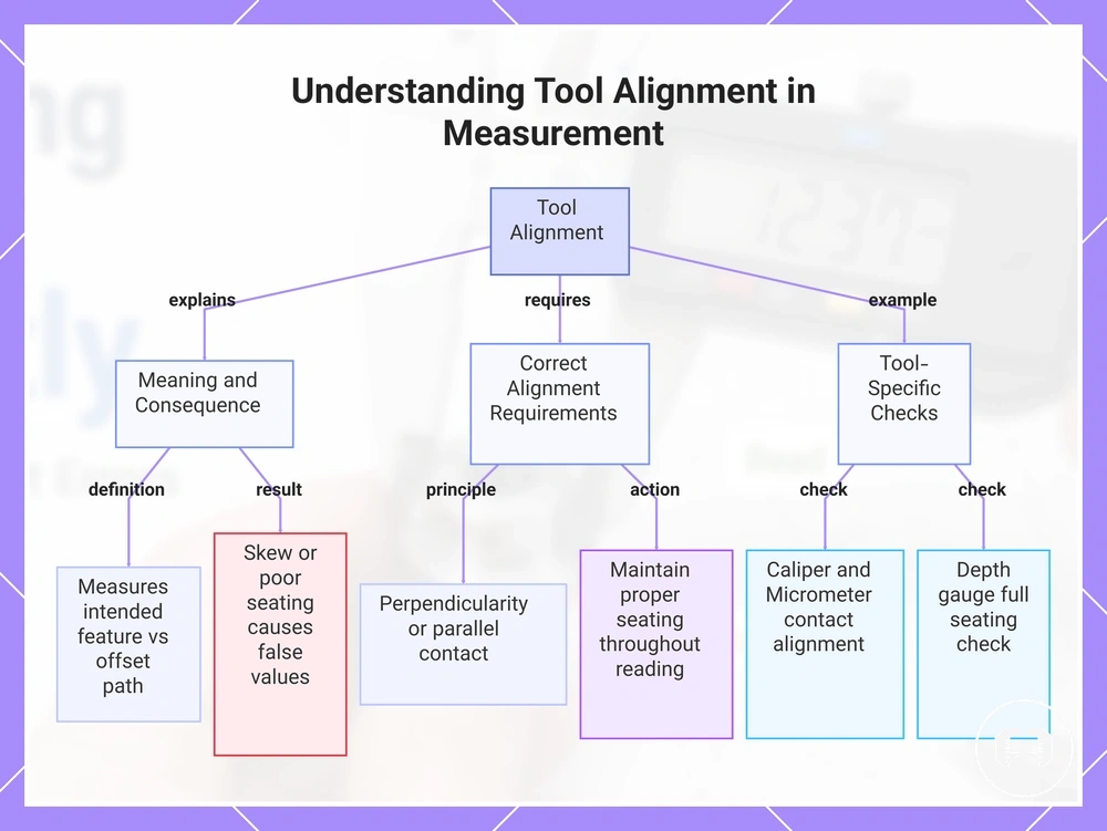
This chart explains what tool alignment means, why it affects measurement accuracy, and how to ensure correct alignment for calipers, micrometers, and depth gauges.
Using common precision measuring tools in practice
Common precision measuring tools follow the same measurement-control principles, but each tool uses a different contact method and reference point. The handling approach should match the tool type because measurement risk and use error may vary with the measured feature, setup, and contact condition.
Each subtype performs a different measurement role while relying on controlled contact and consistent positioning. For broader context about tool types and their uses, understanding each tool's role can help explain why the contact method and reference point change between measurements. The next step is confirming that the selected tool matches the intended measurement task.
The comparison below shows how practical measurement principles apply across common tools without changing the overall approach to controlled measurement.
| Tool | Measurement role | Contact or reference point | Common use risk |
|---|---|---|---|
| Calipers | Outside, inside, and depth measurements | Jaw seating and contact method | Jaw tilt or poor seating may create a use error. |
| Micrometers | External dimensional measurement | Spindle contact and reference point | Incorrect spindle contact may reduce repeatability. |
| Depth gauges | Depth measurement | Reference face and depth rod | An unstable reference point may affect the reading. |
| Dial indicators | Position and movement checks | Probe contact and setup reference | Incorrect probe travel or setup may lead to a use error. |
Calipers for outside, inside, and depth measurements
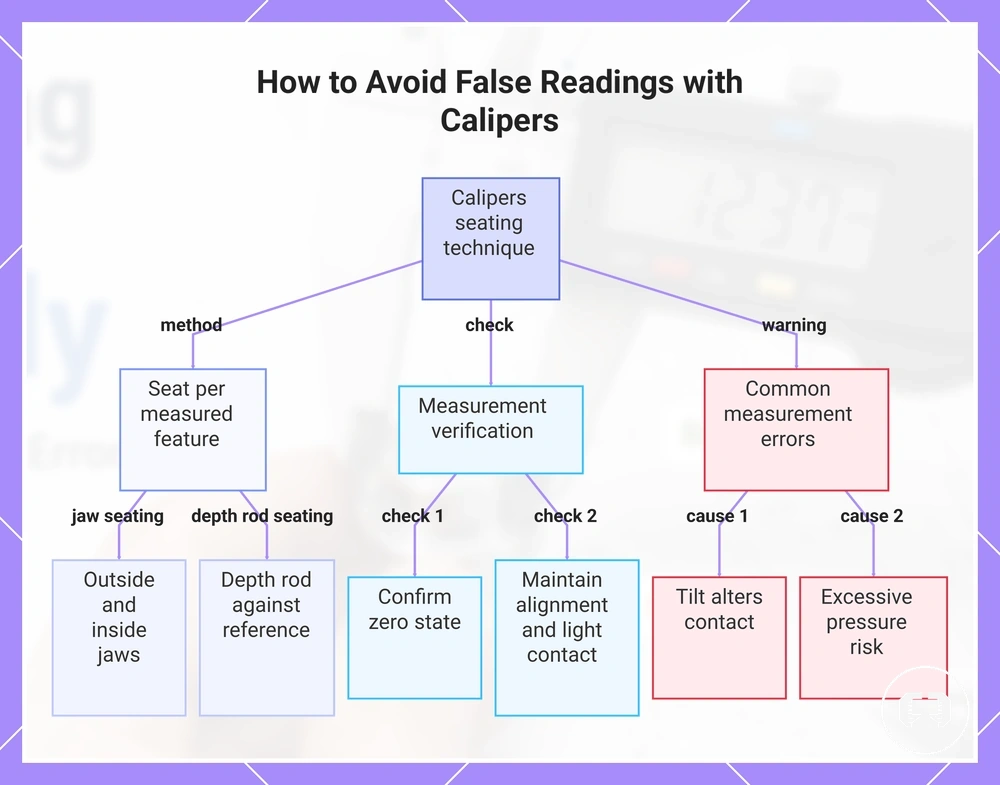
Calipers should be seated according to the measured feature because the outside jaws, inside jaws, and depth rod each use different contact surfaces. Confirming the zero state, maintaining jaw alignment, and applying light contact can help reduce the likelihood of a false reading, although results may vary with the workpiece, setup, and operator technique.
Calipers measure outside, inside, and depth features using different contact surfaces, so each measurement mode requires appropriate seating rather than the same approach. Measuring correctly and reading the result are connected but not identical tasks. For additional guidance on interpreting measurements after correct setup, see how to read measuring tools.
Before accepting a measurement, confirm that the calipers are seated correctly for the intended feature:
- Verify the zero state before placing the calipers on the workpiece.
- Seat the outside jaws or inside jaws squarely against the measured feature while maintaining jaw alignment and light contact.
- Place the depth rod firmly against its reference surface before taking a depth measurement.
- Avoid tilt or excessive pressure because either condition may alter contact and increase the risk of a false reading.
This chart shows the proper seating technique, key checks, and common errors when using calipers to measure outside, inside, and depth features.
Micrometers for controlled contact measurements
Micrometer measurements rely on controlled contact between the anvil, spindle, and measured surface because poor seating or over-tightening may affect the reading. The micrometer frame should remain stable while the spindle closes with controlled contact, since the contact condition may vary with the workpiece and operator technique.
The ratchet or friction thimble helps apply more consistent contact force than tightening the spindle directly, but correct seating still depends on even contact between the anvil, spindle, and measured surface. For example, if a repeat reading remains consistent after reseating the micrometer, the contact condition was more likely applied consistently before accepting the measurement.
Before recording a measurement, complete these local contact checks:
- Seat the measured surface squarely between the anvil and spindle.
- Use the ratchet or friction thimble to establish controlled contact instead of over-tightening.
- Lock the spindle only after the contact position appears stable, when the measurement task requires it.
- Take a repeat reading if seating changes or contact feels inconsistent.
Depth gauges and dial indicators for positional checks
Depth gauge and dial indicator measurements depend on a stable reference surface because both tools verify position through reference control. Reliable positional checks require secure base seating, correct probe contact, a consistent zero reference, and movement that follows the intended travel direction, since rocking or side loading may reduce reading reliability.
Depth gauge: Base seating should remain stable on the reference surface while the measuring element contacts the feature without rocking. A shallow shoulder or uneven base may reduce reading reliability because the reference surface no longer supports consistent depth measurement, so confirm stable seating before accepting the result.
Dial indicator: Probe contact should follow the intended travel direction with perpendicular movement when the measurement requires it. Side loading or angled probe contact may influence the reading because the probe no longer follows the expected movement path, so verify the zero reference and stable setup before relying on the positional check.
Repeatability checks before accepting a measurement
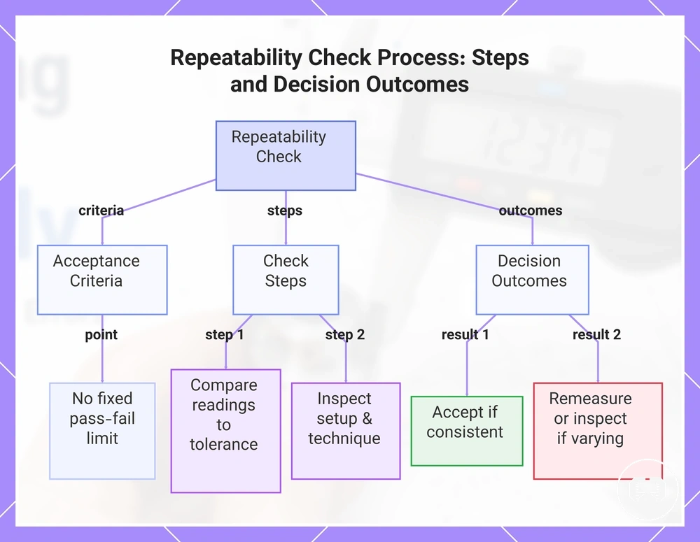
Repeatability checks should accept a measurement only when repeated readings are close enough for the required tolerance and use case. If repeated values vary beyond what the task allows, remeasure or inspect the setup before recording the result.
Acceptable variation depends on the tool, measured feature, material, operator technique, and tolerance requirement rather than a fixed pass-fail limit. The related accuracy and tolerance concepts explain why acceptance criteria should match the intended use case and tolerance.
Repeatability checks compare repeated readings, setup consistency, and the variation range before deciding whether to accept the measurement, remeasure, or inspect the setup. Routine repeat checks may only confirm consistent readings, while continued variation may indicate that setup consistency or operator technique should be reviewed before accepting the result.
Before accepting a measurement, complete this repeatability check:
- Take repeated readings of the same measured feature using the same tool and setup.
- Compare each repeated value with the acceptable variation for the required tolerance.
- Inspect setup consistency if the variation range appears greater than expected for the task.
- Review operator technique if contact pressure, alignment, or handling changes between readings.
- Remeasure or inspect the setup before recording the measurement when repeated readings remain inconsistent.
This chart shows the steps to perform a repeatability check, the criteria for acceptable variation, and the decisions to accept, remeasure, or inspect the setup.
Measurement errors caused by incorrect use
Measurement errors can occur when incorrect use changes the reference, contact, alignment, reading, or measurement environment. If an unexpected reading appears, identify the likely use-related cause before accepting the result because the appropriate correction may depend on the tool, setup, material, or operator technique.
Measurement errors are easier to prevent when each symptom is connected to its likely cause and correction. Comparing the observed error pattern with a focused check helps determine whether the reading should be accepted, repeated, or followed by a prevention action.
| Error pattern | Likely use cause | Immediate check | Prevention action |
|---|---|---|---|
| Inconsistent reading | Reference or contact changed during measurement | Confirm the reference surface and contact points remain unchanged. | Maintain the same reference and contact method for repeated readings. |
| False reading | Incorrect alignment with the measured feature | Verify alignment before taking another reading. | Keep the tool aligned throughout the measurement. |
| Variable repeated readings | Movement, environment, or inconsistent operator technique | Inspect the setup and review handling conditions. | Improve setup stability and use consistent operator technique. |
| Unexpected reading change | Reading method or measurement environment changed | Repeat the measurement under comparable conditions. | Reduce unnecessary changes to the reading process and environment. |
This section covers use-related measurement errors rather than recurring equipment faults or detailed diagnosis. For broader guidance on recurring error patterns, see avoid measuring tool errors, where deeper recurring-error diagnosis is covered.
Zeroing, reference, and range mistakes
A zeroing mistake, reference mistake, or range mistake can make the final measurement unreliable because the baseline or measuring mode is incorrect before the reading begins. When a baseline error is carried into the measurement, value drift may continue until the tool is reset or the reference is rechecked.
A hidden reference mistake may remain unnoticed when repeated readings appear consistent but use the wrong reference face or measuring mode. For example, a measurement may seem repeatable while using an incorrect reference surface, causing value drift until the baseline is checked and corrected.
Check the mistake type before relying on the measured value:
- Zeroing mistake: A wrong zero or baseline can carry the same error into subsequent readings. Reset the baseline before measuring again.
- Reference mistake: A wrong reference face or incorrect measuring mode may produce a false value. Recheck the reference surface before accepting the measurement.
- Range mistake: A tool range that does not suit the measurement may reduce reading reliability. Switch tools or select the appropriate measuring mode before repeating the measurement.
Dirt, burrs, movement, and temperature effects
When a measurement changes even though the setup appears correct, dirt, burrs, movement, or temperature effects may influence contact or the workpiece size rather than the measuring scale. The effect depends on the tool, material, workpiece, and measuring conditions, so inspect the physical condition before accepting a false reading or poor repeatability.
These conditions usually affect the contact between the tool and workpiece or may change their physical size instead of altering the scale itself. Check the surface condition, stability, and thermal condition first, then decide whether cleaning, waiting, stabilizing, or remeasuring is appropriate.
The following checks focus on physical conditions that can influence measurement after the setup appears correct.
| Condition | How it affects contact or size | What to check | What to do next |
|---|---|---|---|
| Dirt or burrs | May create false contact and produce a false reading. | Inspect the contact surfaces and reference faces for surface contamination. | Clean the surfaces and remeasure. |
| Movement or loose parts | May reduce repeatability by changing the contact position. | Confirm the workpiece and tool remain stable during measurement. | Stabilize the setup before measuring again. |
| Hand heat, ambient temperature change, tool expansion, or workpiece expansion | Thermal effects may change the measured size under certain conditions. | Consider recent handling and whether temperatures have had time to stabilize. | Wait for conditions to stabilize, then remeasure if needed. |
After-use handling that protects future accuracy
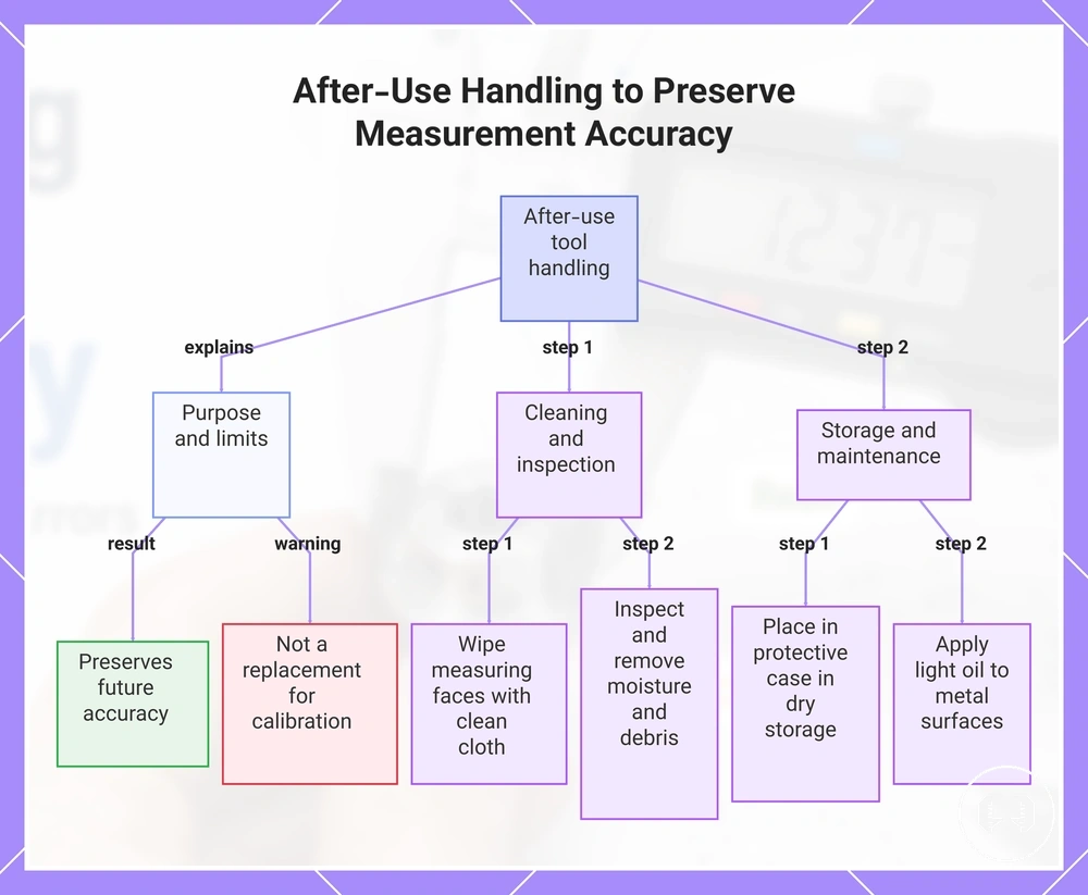
After-use handling helps protect future accuracy by reducing the risk of contamination, corrosion, damage, and reference drift between measurements. Although post-use care cannot correct calibration issues, maintaining good tool condition can help preserve consistent measurement readiness for future use.
Storage and cleaning help preserve the tool condition needed for later measurements because contamination on the measuring faces, moisture, or unsuitable storage may affect future contact conditions. The appropriate care depends on the tool type, material, and storage environment, so use handling methods that suit those conditions.
Readers who need a dedicated maintenance routine can continue to care and storage after use. The checklist below covers only the basic after-use actions that support future accuracy without implying that routine care replaces calibration or inspection.
- Wipe the tool with a clean cleaning cloth to remove dust, residue, and surface contamination.
- Inspect the measuring faces before storage and remove moisture or debris that could increase the risk of corrosion.
- Place the tool in its protective case and keep it in dry storage when it is not in use.
- Apply a light oil to suitable metal surfaces when appropriate for the tool and storage conditions.
- For digital tools, keep the battery compartment and display clean and dry where relevant before storing the tool.
This chart shows why after-use care is important, the essential cleaning and storage steps, and the limitations of post-use handling for measurement tools.